
April 22, 2011
Senior Project: Journal Entry #3
This week has been quite productive. In the beginning of the week I met with my Mentor to discuss how the project's going. I took away from that meeting a better understanding of how I'm going to use my sensors. Other than that, my accomplishments this week include soldering, more soldering, utilizing masking tape and screws, some programming, and finally creating an autonomous car. Today I, for the first time, flipped a switch and my car drove itself forward and backward without human input, making it the dumbest autonomous car I know. Details follow.

April 21, 2011
RoboGames 2011
I spent this past Sunday at RoboGames 2011 up in San Mateo. The point of this excursion was for an opportunity to research robots and autonomy, but it devolved into watching robots mindlessly destroying each other followed by a photo-op with the Mythbuster's Grant Imahara.

At this fiesta of scrap metal, I got some pretty cool footage of not just destruction, but some interesting autonomous robots. They follow after the jump.

At this fiesta of scrap metal, I got some pretty cool footage of not just destruction, but some interesting autonomous robots. They follow after the jump.
April 17, 2011
Senior Project: Journal Entry #2
 |
| Soldering Iron |
But first, the soldering. Using my soldering iron, I attached what are called solid wires to my motors' wires, which are stranded wires.Basically, stranded wire is a bunch of very thin copper wires. Solid wire consists of those stranded wires all dipped in a pot of tin, so that they merge together into a single wire. The advantage of this is easily demonstrated. Stranded wire, because it consists of a mess of different wires, isn't easily placed into a breadboard (which is just a bunch of holes, some of which are connected to each other). Solid wire can be easily placed into a breadboard providing a solid connection.
 |  |
| Stranded Wire | Solid Wire |
 |  |
| Wire in breadboard | Better wire in breadboard |
 |  |

I have ordered what I hope is my last shipment of components. This includes a "shield" for the Arduino, which is just a board that goes above the main board. This shield will allow me to place my breadboard just above the microcontroller, allowing me to save space. I also ordered a motor driver, even though I had hoped I wouldn't need one. The reason behind the motor driver is because a motor's speed and direction is influenced by the amount of current passed into it. With the motor driver, I can use input from the Arduino to influence that speed and direction of two motors, allowing me to turn the wheels left and right and to slow the car down before it hits a wall. The input to the motor driver is what is called Pulse-Width Modulation (PWM), which works by alternating HIGH (5v) and LOW (0v) signals at a certain frequency. This is nice, because I just need to call one command from the Arduino [analogWrite(value)], and it will send that signal until I tell it to stop (I will go more in depth on my programming and code at a later point), so from a coding standpoint it is extremely easy to control my motors. Hopefully, by the end of next week, my car will be able to drive itself!
 |
 |
 |  |
I end this week heading off to the RoboGames. This is a convention held in San Mateo, CA and it is all about robots. There is one event in particular which I am interested in: the Robomagellan. This event is about autonomous robots navigating an obstacle course, which is quite similar to what I hope to accomplish. Other events include a Humanoid robot basketball tournament and autonomous robot fights. I will be taking video and pictures and if I get a chance talking to some of the robot creators in an attempt to learn any thing that might be interesting or help me in this project.
'Til next time!
Next: RoboGames 2011
April 9, 2011
Senior Project: Journal Entry #1
And so starts my regular journal. My accomplishments so far are choosing an RC car, dismantling it, and playing around with its motors.

 My RC car of choice is a Nikko 1:10 scale Nissan Z. I chose this car because it is a good size, the remote controller looked simple, and the car looked cool. It's size is important, because I need to be able to shove my own electronics inside of the body. The simple look of the remote control told me that the electronics inside the car were pretty simple, meaning that the motors the car used should be easy to interface with (as they probably wouldn't be custom-made). And it's always a plus if what you're building looks cool. Having tested the car, I have figured out that the front two wheels rotate to steer the car, and the rear wheels are connected to a motor to move it forward or backward at variable speeds.
The underside of the car contains the battery plug, the on/off switch, and a dial to adjust the steering of the front wheels. I then proceed to unscrew the chassis from the body, by first removing a front and rear plat which hold the two together. After removing these, I am provided a glimpse of the gearbox in the back, as well as some wiring in the front connected to the car's headlights. I do not plan on using these headlights, so after more unscrewing, I cut the wires to the headlights to fully separate the body from the chassis.

 With the chassis now separated, I tried to look for the electronics. I realized, however, that they were inside the chassis and thus I had more screws to remove. Upon doing so, I uncovered the main circuit board for the car, as well as the the main motor. This main motor, which is seen above in the rear gearbox, is what drives the back wheels to make the car go forward. I then came upon an issue I hadn't thought of - how will I steer the car. From looking at the front wheels, I discovered that they work by using a gear system driven by a motor. You turn the motor a little one way or a little the other way to turn the wheels left and right. However, there is a danger in this: if you keep turning the motor, after the wheels have turned as far as they can, you'll damage the motor. So I will need to program in some turning precautions, to keep track of how much the front wheels have turned, so that I'm not turning the motor past its breaking point. Also, in order to keep the wheels aligned, it will be best to reset the wheels to straight before I stop and turn off the car.
 I have almost finished with the dissection of my car. All that is left is to look at the main circuit board. This board, on top, has only a few components - some power transistors, likely which power the motors, several capacitors, possibly used with the radio communication, and some other components. The other side of the board, though, is a mess of different integrated circuits (ICs), which are the little black rectangles, and then a mess of semiconductors, which are all of the smaller rectangles. I cut the wires to the circuit board, which consisted of three wires to each motor, and two wires to the power supply, and then I put the board in a plastic bag as I shouldn't need it anymore.
So I finished my teardown of my RC car, leaving me with a power supply (I hope to be able to reuse the same power supply that powered the RC circuitry with my microcontroller), two motors, and a chassis. I played around with the motors, and discovered that they are nothing more than regular motors, which spin based on how much current is applied to them. I had hoped that I could just plug these into my Arduino and they would work, but after a little more research I believe I will need to purchase a motor driver, which is a circuit built to control motor speed and direction.
Until I get this motor driver, there isn't that much I can do with the motors. So in the mean time, I suppose I'm going to start playing with my sensors and figuring out how best to implement them.
'Til next time.
Next: Journal Entry #2

 My RC car of choice is a Nikko 1:10 scale Nissan Z. I chose this car because it is a good size, the remote controller looked simple, and the car looked cool. It's size is important, because I need to be able to shove my own electronics inside of the body. The simple look of the remote control told me that the electronics inside the car were pretty simple, meaning that the motors the car used should be easy to interface with (as they probably wouldn't be custom-made). And it's always a plus if what you're building looks cool. Having tested the car, I have figured out that the front two wheels rotate to steer the car, and the rear wheels are connected to a motor to move it forward or backward at variable speeds.
The underside of the car contains the battery plug, the on/off switch, and a dial to adjust the steering of the front wheels. I then proceed to unscrew the chassis from the body, by first removing a front and rear plat which hold the two together. After removing these, I am provided a glimpse of the gearbox in the back, as well as some wiring in the front connected to the car's headlights. I do not plan on using these headlights, so after more unscrewing, I cut the wires to the headlights to fully separate the body from the chassis.
 |  |
| Headlight Wires | Rear Gearbox |

 With the chassis now separated, I tried to look for the electronics. I realized, however, that they were inside the chassis and thus I had more screws to remove. Upon doing so, I uncovered the main circuit board for the car, as well as the the main motor. This main motor, which is seen above in the rear gearbox, is what drives the back wheels to make the car go forward. I then came upon an issue I hadn't thought of - how will I steer the car. From looking at the front wheels, I discovered that they work by using a gear system driven by a motor. You turn the motor a little one way or a little the other way to turn the wheels left and right. However, there is a danger in this: if you keep turning the motor, after the wheels have turned as far as they can, you'll damage the motor. So I will need to program in some turning precautions, to keep track of how much the front wheels have turned, so that I'm not turning the motor past its breaking point. Also, in order to keep the wheels aligned, it will be best to reset the wheels to straight before I stop and turn off the car.
 |  |  |
| Front gearbox | Rear gearbox | Main motor with heatsink |

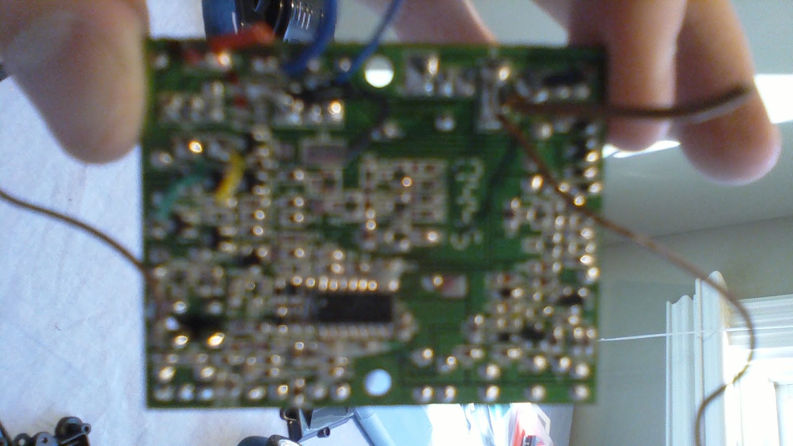 I have almost finished with the dissection of my car. All that is left is to look at the main circuit board. This board, on top, has only a few components - some power transistors, likely which power the motors, several capacitors, possibly used with the radio communication, and some other components. The other side of the board, though, is a mess of different integrated circuits (ICs), which are the little black rectangles, and then a mess of semiconductors, which are all of the smaller rectangles. I cut the wires to the circuit board, which consisted of three wires to each motor, and two wires to the power supply, and then I put the board in a plastic bag as I shouldn't need it anymore.
So I finished my teardown of my RC car, leaving me with a power supply (I hope to be able to reuse the same power supply that powered the RC circuitry with my microcontroller), two motors, and a chassis. I played around with the motors, and discovered that they are nothing more than regular motors, which spin based on how much current is applied to them. I had hoped that I could just plug these into my Arduino and they would work, but after a little more research I believe I will need to purchase a motor driver, which is a circuit built to control motor speed and direction.
Until I get this motor driver, there isn't that much I can do with the motors. So in the mean time, I suppose I'm going to start playing with my sensors and figuring out how best to implement them.
'Til next time.
Next: Journal Entry #2
April 3, 2011
Senior Project: How Stuff Works

Subscribe to:
Posts (Atom)