September 25, 2011

Senior Project: Summer Update

My summer is finally over, bringing with it the start of a new year at school. I hadn't expected to do any more work on my car, but in the summer heat my thoughts drifted to the jumble of wires I'd spent my last weeks of High School playing with. Specifically, I was thinking about the IR sensor and how it could be improved. When I demoed my car, it didn't live up to its expectations (as the video I posted kind of shows). I blame this on how the car was driving on a different surface at a different speed: with changing speeds comes changing reaction times, causing the car to make its turns either too early or too late. Any other explanation for the car's misbehavior would have to be based on it reaching an intelligence level equivalent to that of a rebellious teen. These thoughts I've had about how to improve the IR sensor set up would have been helpful back when I was first building the car, but for now I'll just donate them to the pool of general knowledge.


June 19, 2011

Senior Project Wrap-Up

So two weeks ago I presented my project and demoed my car for my school. I thought it was pretty successful. I have footage of my presentation, as well as a compilation of clips of my car working, all posted below. Also included are two PDFs - one is this whole journal, from start to finish, nicely formatted, and the other is a hardcopy of my presentation. Just in case anyone's interested.

May 30, 2011

Senior Project Bibliography

All websites were accessed between February and May 2011:

Senior Project Reflection

So now I have finished my multiple-month journey of: beginning brilliant battles, triumphing tricky trials, conquering computer crashes, solving slightly serious situations, and writing wonderful weblogs. I am herein required to disclose my most innermost thoughts about this ordeal/experience. My first reaction:  "That was awesome!" It's like coming off a roller-coaster, and wanting to get right back on. To answer my last question first: I would most certainly do this project again. I don't plan on modifying my current car any more, mainly because of the problems I've had with the steering. But some time in the future I will go and find another object to automate. And I will learn from my mistakes. My first mistake is simply choosing my body in haste. I grabbed the first RC car I could find, without doing any research into how it might compare to other cars. This resulted in me choosing a car that moves too fast and doesn't have the best steering mechanism. The ideal car would have four motors, one for each wheel, allowing me to fine-tune how it turns. That would solve all of my steering issues. I certainly plan to stick with the Arduino platform - it was exceptionally easy to learn and worked with all of the different components I picked out. I would change my sensing system, though. I'll have to do more research first. It might benefit me to spend a little more cash to get a higher-end IR sensor, that shoots multiple beams out. That is the sort found on university or corporate autonomous cars. This project has resulted in my learning quite a bit about how autonomous cars should work, and providing plenty of insight on what to do when they don't.

Senior Project Presentation Preview

So When You Come to My Presentation, What Are You Going to Hear? (in 300 words or less):

My project started in my head. I've always imagined driving an autonomous car (paradox, no?), so I thought, why not build a miniature one? There are three components needed to automate a car: a body, a brain, and a pair of eyes. For my body I repurposed an RC car, making use of its chassis, wheels, and motors. My brain is an Arduino, a microcontroller development platform that is essentially a mini-computer. I've written code for the Arduino which is executed when it is turned on. My eyes consist of an infrared sensor mounted on a rotating servo. During the assembly of my car, I had many issues, the main one being with my steering. At first I wasn't sure how to get the wheels to turn without damaging the motor. The solution was to provide as much power as possible. My car still did not steer, though, until I inserted a newly bought battery pack. Once my car could drive itself, it came time for the logic. I devised a simple solution - take a reading from each side of the car, and have it go straight whilst avoiding collisions. There were sporadic issues with the implementation, resulting me in replacing a sonar sensor I'd planned to use with my infrared, but in the end my car looked like magic. Now I'm most certainly not the first person to have achieved such a feat. The idea of autonomous cars dates back to 1939, where they were supposed to move along roads lined with electromagnets and communicate between cars using radios. More recently, cars are packed with computers and sensors, and Google has proven that they are very safe. How soon consumers will own autonomous cars is uncertain, but the Futurama is coming!

Journal Entry #9

And so comes the last entry into this journal. There are a few more posts still to come for this project, but this is the last that I consider a journal entry. My car has come a long way. It went from a car being controlled by radio waves to one being controlled by ultrasound. And it has gone a bit beyond that.


Interview: Jesse Levinson

I recently had the privilege to sit down with Jesse Levinson, a former Crystal Springs Uplands student and now a former Stanfrod PhD student. He started his time at Stanford working on the university's entry into the DARPA 2007 Urban Challenge under Sebastian Thrun, and ended it in charge of the autonomous car program as Thrun helped start the Google car. A teacher of mine who taught him back in the day connected us, and I first met him when I sat in to watch his thesis defense during his final weeks of school.

May 25, 2011

Journal Entry #8.5

After some more progress with my code, and after solving a pair of problems, I have built an autonomous car. It isn't running in my track, yet, and there is still a significant amount of coding to be done, but as the video below shows, it isn't too dumb.

The first problem I solved was one which bothered me from the beginning - steering. I last left this problem thinking that a second motor driver could help get it to steer. At the least, I could run one of the motors off a separate power source. This turns out to be unnecessary. I bought a couple weeks back a newer rechargeable battery for my car, thinking that would solve my issues. I never actually tested it, though. An important lesson: If you think you have a solution, give it a try. Plugging my new battery into my car allowed me to run both motors off a single motor driver. After doing it a bit, though, I started to have issues - the car became sluggish. Thinking back to how I solved the original steering problem (getting the wheels to turn), I turned the drive motor up to full power and voila, it was working great again. The one drawback from this is that it'll be harder to drive my car slow; however, I'm testing on carpet right now, so on a wooden floor I can likely reduce the speed.

The other issue was one I mentioned in my last journal, about needing a decoupling capacitor to protect my sonar sensor when I turned the motors on. Well, I bought that capacitor, and it does its job. The theory behind it is that it works; certainly there is a more technical explanation, likely on Wikipedia, but suffice to say that my sensor works when I add an RC (resistor-capacitor) circuit to its power source (you may note that I actually have two resistors in the circuit. The reason for this is I did not have a 100ohm resistor, which the diagram called for, but two 220ohm resistors. So by putting them in parallel, the equivalent resistance is 110ohms, which is close enough).

Solving those two problems enabled me to produce this cool video:


Journal Entry #8

So, I am nearly there. My presentation is a week from Friday, June 3rd, at 1pm. Until then, I have to make a presentation, interview a (former) PhD student, and still finish my car. Which is nearing completion and looking quite cool. I have attached the sonar sensor to it, and it (mostly) works. This video below shows just how awesome a servo + sensor combination can be:


May 23, 2011

Journal Entry #7

Busy weekend. To start, I have soldered together the remainder of my components - while not yet tested, I'm confident they'll work. The much bigger thing accomplished, however, was the construction of  a track for my car.

To start, soldering. The last time I used a soldering iron, i burned myself and destroyed a sensor because I didn't have enough hands. I decided to rectify that by acquiring another pair of hands - a simple little stand that is able to hold whatever I'm soldering while I solder it. It was very useful, and I was able to solder my motor driver and ultrasonic sensor very quickly. What also helped is that I got a new soldering iron, making sure that it would be hot enough for what I needed to use it for. And it works great.

But the much bigger project was my track. I've been worrying a bit about how I'm going to construct my track, as it needs to be high enough to be read by my sensor, but also has to be able to stand on its own. I've changed my mind frequently while considering my track -  cardboard, poster-board, wood, cardboard again - and thought I had a great solution when my mentor recommended just buying cut pieces of 2"x8" lumber from Home Depot. However, I soon learned just how heave 2"x8"s can be, and with nothing to keep them upright, they could easily fall down and kill my car. So while that was the easiest solution for my track, I feared that it might not be the best.

I settled on another idea offered by my father: take thinner wood (which can't stand on its own but is light) and put supports on it to keep it upright. I found some nice long pieces of molding (the stuff at the base of walls) sitting in my garage that would work. For supports, I ran out to a store and picked up some shelving supports. I spent the next several hours manually sawing my wood into more manageable slices, drilling holes, and sticking a shelving support on each side of the board. While this approach certainly took more time, my result is a very decent-looking, and very sturdy, track.

The design of my track consists of ten pieces of wood on the outside with one piece down the middle. The perimeter of the track at the most will be 38 feet - this is slightly large, but gives my car plenty of room to work with. Each side is made up of two 5-foot pieces, and the ends are composed of three 3-foot pieces. I am able to adjust the size of the ends, as I am not certain how much room my car is going to need to turn. As I progress more on my code, I will set up my track and try to get my car to run around it. We'll see how it goes.

With that large part done, the remainder of my time is being spent coding. Code, test, repeat. By the end of this week my car will be fully functionally awesome. At which point, I'll certainly upload a video of it working.

So until next time.

Next: Journal Entry #8

May 19, 2011

Journal Entry #6

This entry comes with some unfortunate lessons learned that have set me back a bit of time, followed by much cool progress. As of my last entry, I had only tested my IR sensors, even though I'd decided I wasn't going to use them. So when the time came to test my Ultrasonic sensor, I'd discovered that the header pins I'd soldered to it oh-so-long ago were in backwards (I mean, who'd have guessed that there's a right way to doing something?) So in my attempt to fix that issue, I kind of broke the sensor. After that fiasco, I devoted myself fully to hardware, no more soldering: I prepared my pieces of wood so that I can mount my electronics on my car. Once again I discovered that there's a right way to doing something - which I didn't do, though this only resulted in my drilling four unnecessary holes.


May 13, 2011

Journal Entry #5

So far this week, I have cut some wood to size to prepare it for attachment to my car, and I have tested my IR sensors to my satisfaction. Repeating a version of my IR sensor experiment that I conducted previously, I have gathered enough data that I feel I have a good equation to use with my sensors if I need to use them.

So here is the wood I have cut; it's not too exciting, but soon I'll be putting holes in it, and then it gets much more exciting. The type of wood is called Masonite - it is commonly used in tool shops as the top of a work bench, because it is strong and its top is nice and clean. I happened to have a couple sheets, so I figured it would work nicely to support my Arduino. My Arduino will not be screwed directly onto the board, as it would be damaged where its bottom scratches against the board. I have plastic standoffs which screws go through to support the Arduino 3/4" above the platform

Nuts and Standoffs
For the front of the car, where the Ultrasonic sensor and its servo will go, I am still figuring out what needs to be done. The sensor has two holes for screws, which I plan to use with standoffs to place a wooden platform behind the sensor, so that I can screw that platform down. It will likely be placed on a piece of wood which will be screwed into the servo. I'm still working out the details of what happens with the servo, but my current thought is to do a little more woodworking to create a stand for it to be placed into.

My IR sensors have me puzzled as to where they should be placed, in part because I got the wrong ones, requiring me to place them eight inches away from what I want them to measure. However, I am currently of the ideology that I only need to use one sensor to make this car go, so unless necessity dictates otherwise, I'm going to forget about mounting my IR sensors.

The infinite uses of LEGOs!
Speaking of IR sensors, I have finally cracked their distance algorithm. While looking for information about Ultrasonic sensors I came upon this website, which claimed that IR sensors are better than Ultrasonic, so I simply chose to buy the kind he was using (which ended up being a mistake).


His equation for converting the output of the sensor to a distance is as follows:


However, that equation didn't produce accurate results with my sensors. So from repeating the same experiments I did before with the sensor, I came up with the below equation:


They are similar enough, which I take as a good sign. However, I also found a more accurate equation dealing with fourth-degree polynomials:


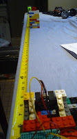
So how I came up with these. I repeated the experiment of taking distance measurements from the sensor over a range of distance. I took twenty measurements per distance, and repeated that over two feet. I have had issues previously where my sensor would be aiming at the ground, so there would be a maximum distance on it. And also I occasionally had it pointing too much up, so that it would aim over the target. My resolution to this was to aim the sensors up, and use a sheet of paper so that the sensors couldn't shoot too high.


I took measurements for both sensors, as I discovered they didn't produce identical results. Using Excel, I graphed both of their results, found the average, and then graphed that average. Using Excel's built in regression I was able to come up with equations which produce accurate results over the range I care about, which is 8 to 32 inches (as if I did use these on my car, I don't think there's a reason to care about anything more than two feet away).


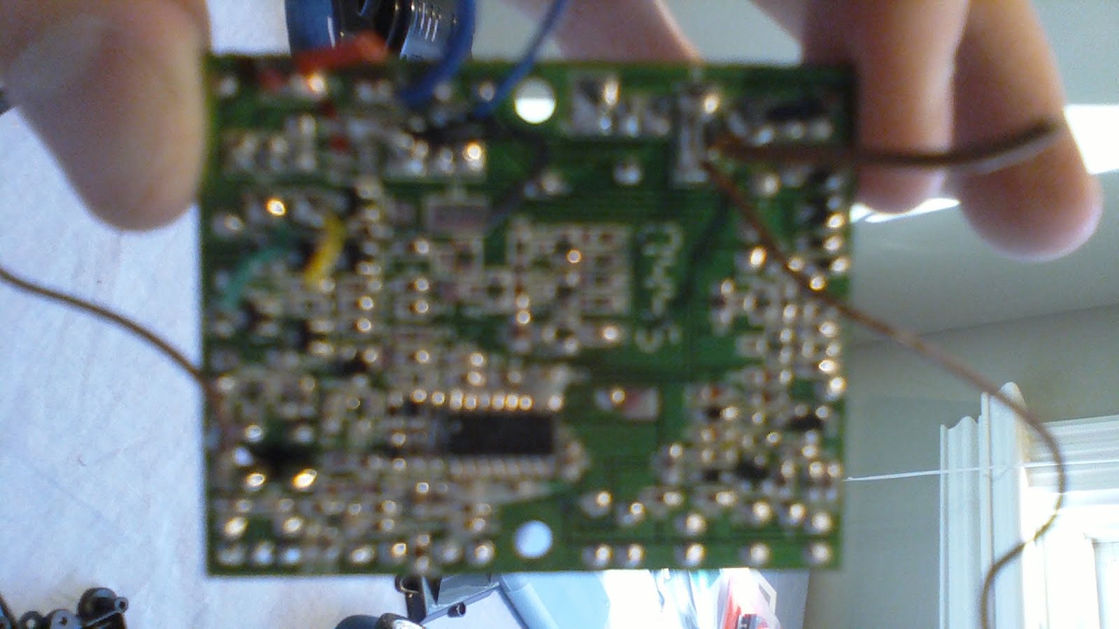
I took an interesting picture while doing this. Cameras, it turns out, can see IR light. However, they view the light as bluish, when it really should be redder. So in this picture you can see the IR source in the back of the sensor.

What's next? I need to finish mounting the Arduino, which involves drilling some holes. Then I need to continue to work on mounting the Ultrasonic sensor. My new motor driver has arrived, so I have some soldering to do, and then hopefully my car works. A final issue I need to solve is that of the track - I plan on stopping by a Home Depot and looking around their gardening supplies; maybe they'll have something. If not, Poster-board should work just fine.

So 'til next time.

Next: Journal Entry #6

May 9, 2011

Senior Project: Journal Entry #4

These past two weeks have been spent solving problems. The major problem was steering; at my last journal entry, my car was having a tough time turning the wheels. The other problem I have been dealing with is figuring out how I am going to mount my Arduino and sensors. Afraid I wouldn't have any decent pictures to include in this post, I sketched up a model of my car in Google SketchUp both for the purposes of being awesome as well as helping me visualize what hardware I will need to finish this car. The model isn't exactly to-size, but it conveys the general feel of my automobile.

And when compared to an actual picture, it isn't too far off.


As might be noticed, this picture of my car has an added piece of plastic in the front and back. These are the car's bumpers , which allow little children to ram RC cars into brick walls repeatedly. I added these back to my car because they will provide me a some more space to work with (you can see a 9V battery mounted on the back piece), which will be helpful when the time comes to mount the sensors.

But first, the steering. To figure out what the car normally does when it steers, I hooked the old RC circuit back up to the steering motor and played around. My first test was to make sure the circuit worked, so I used it to turn the front wheels left and right. All good. I then took the front motor out of the car and told it to turn. I discovered, whilst doing this, that the motor was being spun at a constant speed in one direction or the other. At first, I thought I would need to specifically calculate the speed at which this motor turned. I started by seeing what happens when I ran the motor at full power from my circuit. Well, guess what, with the maximum power the wheels turned properly and there was no sign that the motor was killing itself. If I gave the motor less power, then it would start to make an annoying sound (I thought that the sound meant the motor was spinning too hard, but that wouldn't make sense). So I just set the power to maximum, and my car steers!

Or so I'd thought. When the car is sitting on its pedestal of LEGOs, it steers just fine. When it is placed on the ground, well, problems arise as the wheels refuse to turn all of the way. After messing around with various thingies and other various thingies, I came upon a realization: once on the ground, the front wheels won't turn all of the way if the back wheels are also spinning. I took my ammeter out to perform measurements on what was happening to the front motor, and it turns out that when friction is applied to a motor, it will draw lots more current. Meaning, when the back wheels are spinning on the ground, the friction causes them to have to draw more power to be able to keep spinning, and part of that extra power comes from the steering motor. My first thought was that I could program stuff into the software that stopped the rear wheels before making a turn. I have realized though that a software solution to a problem like this is not ideal. I looked back at the RC circuit I'd taken out and remembered that it used two motor drivers, one for each motor. The two motor drivers gave me an idea - if I separate the two motors, run them from different chips, maybe they will be able to work in tandem? I have ordered a second motor driver to find out, though I will not know if it will work until, well, it works. In the event that the second motor driver does not solve my steering issues, my next idea is to give them each different power supplies, which I know will fix the problem of current drain (one interesting issue that current drain brings up is what effect it will have on my sensors and the servo. If worst comes to worst, I could use a 9V battery for each motor, and then use the rechargeable battery for the Arduino, sensors, and the servo).

But on the note of sensors, I have been divining ways of mounting them to my car. There are four places in the rear of the car into which I can place screws. Two of them had a use, the other two I think are vestigial organs. But the four are arranged nicely enough that I can place a piece of wood over the top and use the holes to screw it down. This piece of wood is where I plan to mount my Arduino.

With my Arduino mounted, I'm left with three sensors. I probably already mentioned how they will be used, but I'll go over it again. I'm placing my Ultrasonic sensor on a servo, and will place this servo near the front of the car. The two IR sensors will be placed to cover the two sides of the car; however, I cannot place them directly on the side. As I got the wrong kind of sensor, they have a minimum range of 15cm (6in), meaning that any readings inside that distance will be garbage. To solve that issue, I need to place them 15cm away from the edge of the car. My most likely solution will be to place them back near the Arduino, and pointing at an angle across the car; for that, I will need to use more wood to create a platform to screw them into.

Admittedly, the last two weeks have been slow, with not too much physical progress. However, I am picking it up now and will probably be writing more entries to avoid writing weekly novels. My next entry should cover the assembly of my second motor driver and whether or not it is a success.

'Til next time.

Next: Journal Entry #5

Sources: [1]

April 22, 2011

Senior Project: Journal Entry #3

This week has been quite productive. In the beginning of the week I met with my Mentor to discuss how the project's going. I took away from that meeting a better understanding of how I'm going to use my sensors. Other than that, my accomplishments this week include soldering, more soldering, utilizing masking tape and screws, some programming, and finally creating an autonomous car. Today I, for the first time, flipped a switch and my car drove itself forward and backward without human input, making it the dumbest autonomous car I know. Details follow.


April 21, 2011

RoboGames 2011

I spent this past Sunday at RoboGames 2011 up in San Mateo. The point of this excursion was for an opportunity to research robots and autonomy, but it devolved into watching robots mindlessly destroying each other followed by a photo-op with the Mythbuster's Grant Imahara.


At this fiesta of scrap metal, I got some pretty cool footage of not just destruction, but some interesting autonomous robots. They follow after the jump.

April 17, 2011

Senior Project: Journal Entry #2

Soldering Iron
This week, my accomplishments were done mainly from my friendly soldering iron. I soldered some additional wires to the wires already present on the motors; it doesn't seem like much, but by doing so, I am almost ready to put the motors back where they belong, after which I will be able to screw the car back together. I did a little more than just soldering, though; I tested one of my IR sensors to slightly unsatisfactory results.


But first, the soldering. Using my soldering iron, I attached what are called solid wires to my motors' wires, which are stranded wires.Basically, stranded wire is a bunch of very thin copper wires. Solid wire consists of those stranded wires all dipped in a pot of tin, so that they merge together into a single wire. The advantage of this is easily demonstrated. Stranded wire, because it consists of a mess of different wires, isn't easily placed into a breadboard (which is just a bunch of holes, some of which are connected to each other). Solid wire can be easily placed into a breadboard providing a solid connection.

Stranded WireSolid Wire
Wire in breadboardBetter wire in breadboard

In addition to extending my motors, I added pins onto my Ultrasonic sensor for the same reason - with these pins, I can plug the sensor directly into a breadboard, or (with some wires I ordered) I can plug the pins into wires which themselves will plug into a breadboard. There are seven pins for this sensor, but I will only need to use three of them. I soldered the full seven pins on, however, in the event that I need to change which pins I need to use. I don't need to resolder anything on the sensor, I just need to change which wires are plugged in.


I have ordered what I hope is my last shipment of components. This includes a "shield" for the Arduino, which is just a board that goes above the main board. This shield will allow me to place my breadboard just above the microcontroller, allowing me to save space. I also ordered a motor driver, even though I had hoped I wouldn't need one. The reason behind the motor driver is because a motor's speed and direction is influenced by the amount of current passed into it. With the motor driver, I can use input from the Arduino to influence that speed and direction of two motors, allowing me to turn the wheels left and right and to slow the car down before it hits a wall. The input to the motor driver is what is called Pulse-Width Modulation (PWM), which works by alternating HIGH (5v) and LOW (0v) signals at a certain frequency. This is nice, because I just need to call one command from the Arduino [analogWrite(value)], and it will send that signal until I tell it to stop (I will go more in depth on my programming and code at a later point), so from a coding standpoint it is extremely easy to control my motors. Hopefully, by the end of next week, my car will be able to drive itself!

And now comes the part where I talk about my trials and tribulations encountered this past week. Firstly, soldering always comes with its own risks, and I burned my fingers a couple times while doing my work. I got a new soldering iron, so hopefully next time I go to solder it won't be as bad. And then there is my attempt to start using my IR sensors. As I said a few weeks back, these sensors work by returning a voltage relating to the free distance in front of the sensor. The plot of this voltage isn't very nice - it isn't quite exponential decay, it isn't quite a logarithmic graph, and it isn't quite a polynomial function. I set up an experiment using the engineer's must trustworthy tool - LEGOs - in an attempt to gather data to reproduce the above graph. In order to use this sensor, I will need some way to convert the voltage received from the sensor to a distance value. There are two ways to do this: I can have a table of voltages, so when I receive, say, 2V from the sensor, I can look it up in the table to discover that the object is 30cm in front of the sensor. This way requires no knowledge of mathematics, but it takes up precious memory. The other way is to come up with some fancy function to convert Volts to Centimeters. I'm going with the later method, but in order to come up with that function, I will need to perform more tests, including making sure both of my sensors give the same readings.

I end this week heading off to the RoboGames. This is a convention held in San Mateo, CA and it is all about robots. There is one event in particular which I am interested in: the Robomagellan. This event is about autonomous robots navigating an obstacle course, which is quite similar to what I hope to accomplish. Other events include a Humanoid robot basketball tournament and autonomous robot fights. I will be taking video and pictures and if I get a chance talking to some of the robot creators in an attempt to learn any thing that might be interesting or help me in this project.

'Til next time!

Next: RoboGames 2011

April 9, 2011

Senior Project: Journal Entry #1

And so starts my regular journal. My accomplishments so far are choosing an RC car, dismantling it, and playing around with its motors.

My RC car of choice is a Nikko 1:10 scale Nissan Z. I chose this car because it is a good size, the remote controller looked simple, and the car looked cool. It's size is important, because I need to be able to shove my own electronics inside of the body. The simple look of the remote control told me that the electronics inside the car were pretty simple, meaning that the motors the car used should be easy to interface with (as they probably wouldn't be custom-made). And it's always a plus if what you're building looks cool. Having tested the car, I have figured out that the front two wheels rotate to steer the car, and the rear wheels are connected to a motor to move it forward or backward at variable speeds.

The underside of the car contains the battery plug, the on/off switch, and a dial to adjust the steering of the front wheels. I then proceed to unscrew the chassis from the body, by first removing a front and rear plat which hold the two together. After removing these, I am provided a glimpse of the gearbox in the back, as well as some wiring in the front connected to the car's headlights. I do not plan on using these headlights, so after more unscrewing, I cut the wires to the headlights to fully separate the body from the chassis.

Headlight WiresRear Gearbox

With the chassis now separated, I tried to look for the electronics. I realized, however, that they were inside the chassis and thus I had more screws to remove. Upon doing so, I uncovered the main circuit board for the car, as well as the the main motor. This main motor, which is seen above in the rear gearbox, is what drives the back wheels to make the car go forward. I then came upon an issue I hadn't thought of - how will I steer the car. From looking at the front wheels, I discovered that they work by using a gear system driven by a motor. You turn the motor a little one way or a little the other way to turn the wheels left and right. However, there is a danger in this: if you keep turning the motor, after the wheels have turned as far as they can, you'll damage the motor. So I will need to program in some turning precautions, to keep track of how much the front wheels have turned, so that I'm not turning the motor past its breaking point. Also, in order to keep the wheels aligned, it will be best to reset the wheels to straight before I stop and turn off the car.

Front gearboxRear gearboxMain motor with heatsink


I have almost finished with the dissection of my car. All that is left is to look at the main circuit board. This board, on top, has only a few components - some power transistors, likely which power the motors, several capacitors, possibly used with the radio communication, and some other components. The other side of the board, though, is a mess of different integrated circuits (ICs), which are the little black rectangles, and then a mess of semiconductors, which are all of the smaller rectangles. I cut the wires to the circuit board, which consisted of three wires to each motor, and two wires to the power supply, and then I put the board in a plastic bag as I shouldn't need it anymore.

So I finished my teardown of my RC car, leaving me with a power supply (I hope to be able to reuse the same power supply that powered the RC circuitry with my microcontroller), two motors, and a chassis. I played around with the motors, and discovered that they are nothing more than regular motors, which spin based on how much current is applied to them. I had hoped that I could just plug these into my Arduino and they would work, but after a little more research I believe I will need to purchase a motor driver, which is a circuit built to control motor speed and direction.

Until I get this motor driver, there isn't that much I can do with the motors. So in the mean time, I suppose I'm going to start playing with my sensors and figuring out how best to implement them.

'Til next time.

Next: Journal Entry #2