All websites were accessed between February and May 2011:
May 30, 2011
Senior Project Reflection
So now I have finished my multiple-month journey of: beginning brilliant battles, triumphing tricky trials, conquering computer crashes, solving slightly serious situations, and writing wonderful weblogs. I am herein required to disclose my most innermost thoughts about this ordeal/experience. My first reaction: "That was awesome!" It's like coming off a roller-coaster, and wanting to get right back on. To answer my last question first: I would most certainly do this project again. I don't plan on modifying my current car any more, mainly because of the problems I've had with the steering. But some time in the future I will go and find another object to automate. And I will learn from my mistakes. My first mistake is simply choosing my body in haste. I grabbed the first RC car I could find, without doing any research into how it might compare to other cars. This resulted in me choosing a car that moves too fast and doesn't have the best steering mechanism. The ideal car would have four motors, one for each wheel, allowing me to fine-tune how it turns. That would solve all of my steering issues. I certainly plan to stick with the Arduino platform - it was exceptionally easy to learn and worked with all of the different components I picked out. I would change my sensing system, though. I'll have to do more research first. It might benefit me to spend a little more cash to get a higher-end IR sensor, that shoots multiple beams out. That is the sort found on university or corporate autonomous cars. This project has resulted in my learning quite a bit about how autonomous cars should work, and providing plenty of insight on what to do when they don't.
Senior Project Presentation Preview
So When You Come to My Presentation, What Are You Going to Hear? (in 300 words or less):
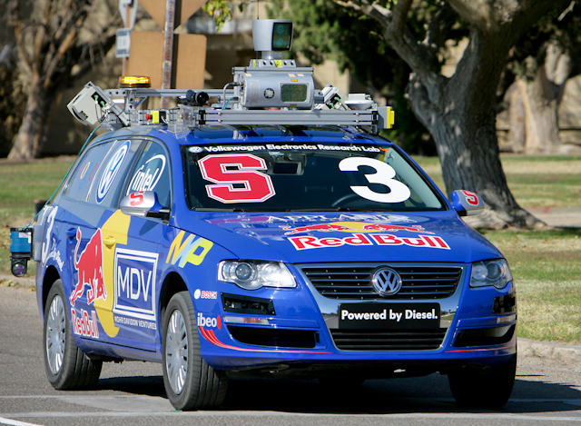
My project started in my head. I've always imagined driving an autonomous car (paradox, no?), so I thought, why not build a miniature one? There are three components needed to automate a car: a body, a brain, and a pair of eyes. For my body I repurposed an RC car, making use of its chassis, wheels, and motors. My brain is an Arduino, a microcontroller development platform that is essentially a mini-computer. I've written code for the Arduino which is executed when it is turned on. My eyes consist of an infrared sensor mounted on a rotating servo. During the assembly of my car, I had many issues, the main one being with my steering. At first I wasn't sure how to get the wheels to turn without damaging the motor. The solution was to provide as much power as possible. My car still did not steer, though, until I inserted a newly bought battery pack. Once my car could drive itself, it came time for the logic. I devised a simple solution - take a reading from each side of the car, and have it go straight whilst avoiding collisions. There were sporadic issues with the implementation, resulting me in replacing a sonar sensor I'd planned to use with my infrared, but in the end my car looked like magic. Now I'm most certainly not the first person to have achieved such a feat. The idea of autonomous cars dates back to 1939, where they were supposed to move along roads lined with electromagnets and communicate between cars using radios. More recently, cars are packed with computers and sensors, and Google has proven that they are very safe. How soon consumers will own autonomous cars is uncertain, but the Futurama is coming!
My project started in my head. I've always imagined driving an autonomous car (paradox, no?), so I thought, why not build a miniature one? There are three components needed to automate a car: a body, a brain, and a pair of eyes. For my body I repurposed an RC car, making use of its chassis, wheels, and motors. My brain is an Arduino, a microcontroller development platform that is essentially a mini-computer. I've written code for the Arduino which is executed when it is turned on. My eyes consist of an infrared sensor mounted on a rotating servo. During the assembly of my car, I had many issues, the main one being with my steering. At first I wasn't sure how to get the wheels to turn without damaging the motor. The solution was to provide as much power as possible. My car still did not steer, though, until I inserted a newly bought battery pack. Once my car could drive itself, it came time for the logic. I devised a simple solution - take a reading from each side of the car, and have it go straight whilst avoiding collisions. There were sporadic issues with the implementation, resulting me in replacing a sonar sensor I'd planned to use with my infrared, but in the end my car looked like magic. Now I'm most certainly not the first person to have achieved such a feat. The idea of autonomous cars dates back to 1939, where they were supposed to move along roads lined with electromagnets and communicate between cars using radios. More recently, cars are packed with computers and sensors, and Google has proven that they are very safe. How soon consumers will own autonomous cars is uncertain, but the Futurama is coming!
Journal Entry #9
And so comes the last entry into this journal. There are a few more posts still to come for this project, but this is the last that I consider a journal entry. My car has come a long way. It went from a car being controlled by radio waves to one being controlled by ultrasound. And it has gone a bit beyond that.


Interview: Jesse Levinson
I recently had the privilege to sit down with Jesse Levinson, a former Crystal Springs Uplands student and now a former Stanfrod PhD student. He started his time at Stanford working on the university's entry into the DARPA 2007 Urban Challenge under Sebastian Thrun, and ended it in charge of the autonomous car program as Thrun helped start the Google car. A teacher of mine who taught him back in the day connected us, and I first met him when I sat in to watch his thesis defense during his final weeks of school.
May 25, 2011
Journal Entry #8.5
After some more progress with my code, and after solving a pair of problems, I have built an autonomous car. It isn't running in my track, yet, and there is still a significant amount of coding to be done, but as the video below shows, it isn't too dumb.
 The first problem I solved was one which bothered me from the beginning - steering. I last left this problem thinking that a second motor driver could help get it to steer. At the least, I could run one of the motors off a separate power source. This turns out to be unnecessary. I bought a couple weeks back a newer rechargeable battery for my car, thinking that would solve my issues. I never actually tested it, though. An important lesson: If you think you have a solution, give it a try. Plugging my new battery into my car allowed me to run both motors off a single motor driver. After doing it a bit, though, I started to have issues - the car became sluggish. Thinking back to how I solved the original steering problem (getting the wheels to turn), I turned the drive motor up to full power and voila, it was working great again. The one drawback from this is that it'll be harder to drive my car slow; however, I'm testing on carpet right now, so on a wooden floor I can likely reduce the speed.
 The other issue was one I mentioned in my last journal, about needing a decoupling capacitor to protect my sonar sensor when I turned the motors on. Well, I bought that capacitor, and it does its job. The theory behind it is that it works; certainly there is a more technical explanation, likely on Wikipedia, but suffice to say that my sensor works when I add an RC (resistor-capacitor) circuit to its power source (you may note that I actually have two resistors in the circuit. The reason for this is I did not have a 100ohm resistor, which the diagram called for, but two 220ohm resistors. So by putting them in parallel, the equivalent resistance is 110ohms, which is close enough).
Solving those two problems enabled me to produce this cool video:
Journal Entry #8
So, I am nearly there. My presentation is a week from Friday, June 3rd, at 1pm. Until then, I have to make a presentation, interview a (former) PhD student, and still finish my car. Which is nearing completion and looking quite cool. I have attached the sonar sensor to it, and it (mostly) works. This video below shows just how awesome a servo + sensor combination can be:
May 23, 2011
Journal Entry #7
Busy weekend. To start, I have soldered together the remainder of my components - while not yet tested, I'm confident they'll work. The much bigger thing accomplished, however, was the construction of a track for my car.
 To start, soldering. The last time I used a soldering iron, i burned myself and destroyed a sensor because I didn't have enough hands. I decided to rectify that by acquiring another pair of hands - a simple little stand that is able to hold whatever I'm soldering while I solder it. It was very useful, and I was able to solder my motor driver and ultrasonic sensor very quickly. What also helped is that I got a new soldering iron, making sure that it would be hot enough for what I needed to use it for. And it works great.
 But the much bigger project was my track. I've been worrying a bit about how I'm going to construct my track, as it needs to be high enough to be read by my sensor, but also has to be able to stand on its own. I've changed my mind frequently while considering my track - cardboard, poster-board, wood, cardboard again - and thought I had a great solution when my mentor recommended just buying cut pieces of 2"x8" lumber from Home Depot. However, I soon learned just how heave 2"x8"s can be, and with nothing to keep them upright, they could easily fall down and kill my car. So while that was the easiest solution for my track, I feared that it might not be the best.

 I settled on another idea offered by my father: take thinner wood (which can't stand on its own but is light) and put supports on it to keep it upright. I found some nice long pieces of molding (the stuff at the base of walls) sitting in my garage that would work. For supports, I ran out to a store and picked up some shelving supports. I spent the next several hours manually sawing my wood into more manageable slices, drilling holes, and sticking a shelving support on each side of the board. While this approach certainly took more time, my result is a very decent-looking, and very sturdy, track.
 The design of my track consists of ten pieces of wood on the outside with one piece down the middle. The perimeter of the track at the most will be 38 feet - this is slightly large, but gives my car plenty of room to work with. Each side is made up of two 5-foot pieces, and the ends are composed of three 3-foot pieces. I am able to adjust the size of the ends, as I am not certain how much room my car is going to need to turn. As I progress more on my code, I will set up my track and try to get my car to run around it. We'll see how it goes.
 With that large part done, the remainder of my time is being spent coding. Code, test, repeat. By the end of this week my car will be fully functionally awesome. At which point, I'll certainly upload a video of it working.
So until next time.
Next: Journal Entry #8
 To start, soldering. The last time I used a soldering iron, i burned myself and destroyed a sensor because I didn't have enough hands. I decided to rectify that by acquiring another pair of hands - a simple little stand that is able to hold whatever I'm soldering while I solder it. It was very useful, and I was able to solder my motor driver and ultrasonic sensor very quickly. What also helped is that I got a new soldering iron, making sure that it would be hot enough for what I needed to use it for. And it works great.
 But the much bigger project was my track. I've been worrying a bit about how I'm going to construct my track, as it needs to be high enough to be read by my sensor, but also has to be able to stand on its own. I've changed my mind frequently while considering my track - cardboard, poster-board, wood, cardboard again - and thought I had a great solution when my mentor recommended just buying cut pieces of 2"x8" lumber from Home Depot. However, I soon learned just how heave 2"x8"s can be, and with nothing to keep them upright, they could easily fall down and kill my car. So while that was the easiest solution for my track, I feared that it might not be the best.
 I settled on another idea offered by my father: take thinner wood (which can't stand on its own but is light) and put supports on it to keep it upright. I found some nice long pieces of molding (the stuff at the base of walls) sitting in my garage that would work. For supports, I ran out to a store and picked up some shelving supports. I spent the next several hours manually sawing my wood into more manageable slices, drilling holes, and sticking a shelving support on each side of the board. While this approach certainly took more time, my result is a very decent-looking, and very sturdy, track.
 With that large part done, the remainder of my time is being spent coding. Code, test, repeat. By the end of this week my car will be fully functionally awesome. At which point, I'll certainly upload a video of it working.
So until next time.
Next: Journal Entry #8
May 19, 2011
Journal Entry #6
This entry comes with some unfortunate lessons learned that have set me back a bit of time, followed by much cool progress. As of my last entry, I had only tested my IR sensors, even though I'd decided I wasn't going to use them. So when the time came to test my Ultrasonic sensor, I'd discovered that the header pins I'd soldered to it oh-so-long ago were in backwards (I mean, who'd have guessed that there's a right way to doing something?) So in my attempt to fix that issue, I kind of broke the sensor. After that fiasco, I devoted myself fully to hardware, no more soldering: I prepared my pieces of wood so that I can mount my electronics on my car. Once again I discovered that there's a right way to doing something - which I didn't do, though this only resulted in my drilling four unnecessary holes.


May 13, 2011
Journal Entry #5
So far this week, I have cut some wood to size to prepare it for attachment to my car, and I have tested my IR sensors to my satisfaction. Repeating a version of my IR sensor experiment that I conducted previously, I have gathered enough data that I feel I have a good equation to use with my sensors if I need to use them.
 So here is the wood I have cut; it's not too exciting, but soon I'll be putting holes in it, and then it gets much more exciting. The type of wood is called Masonite - it is commonly used in tool shops as the top of a work bench, because it is strong and its top is nice and clean. I happened to have a couple sheets, so I figured it would work nicely to support my Arduino. My Arduino will not be screwed directly onto the board, as it would be damaged where its bottom scratches against the board. I have plastic standoffs which screws go through to support the Arduino 3/4" above the platform
For the front of the car, where the Ultrasonic sensor and its servo will go, I am still figuring out what needs to be done. The sensor has two holes for screws, which I plan to use with standoffs to place a wooden platform behind the sensor, so that I can screw that platform down. It will likely be placed on a piece of wood which will be screwed into the servo. I'm still working out the details of what happens with the servo, but my current thought is to do a little more woodworking to create a stand for it to be placed into.
My IR sensors have me puzzled as to where they should be placed, in part because I got the wrong ones, requiring me to place them eight inches away from what I want them to measure. However, I am currently of the ideology that I only need to use one sensor to make this car go, so unless necessity dictates otherwise, I'm going to forget about mounting my IR sensors.
Speaking of IR sensors, I have finally cracked their distance algorithm. While looking for information about Ultrasonic sensors I came upon this website, which claimed that IR sensors are better than Ultrasonic, so I simply chose to buy the kind he was using (which ended up being a mistake).
His equation for converting the output of the sensor to a distance is as follows:

However, that equation didn't produce accurate results with my sensors. So from repeating the same experiments I did before with the sensor, I came up with the below equation:

They are similar enough, which I take as a good sign. However, I also found a more accurate equation dealing with fourth-degree polynomials:

 So how I came up with these. I repeated the experiment of taking distance measurements from the sensor over a range of distance. I took twenty measurements per distance, and repeated that over two feet. I have had issues previously where my sensor would be aiming at the ground, so there would be a maximum distance on it. And also I occasionally had it pointing too much up, so that it would aim over the target. My resolution to this was to aim the sensors up, and use a sheet of paper so that the sensors couldn't shoot too high.
I took measurements for both sensors, as I discovered they didn't produce identical results. Using Excel, I graphed both of their results, found the average, and then graphed that average. Using Excel's built in regression I was able to come up with equations which produce accurate results over the range I care about, which is 8 to 32 inches (as if I did use these on my car, I don't think there's a reason to care about anything more than two feet away).

 I took an interesting picture while doing this. Cameras, it turns out, can see IR light. However, they view the light as bluish, when it really should be redder. So in this picture you can see the IR source in the back of the sensor.
What's next? I need to finish mounting the Arduino, which involves drilling some holes. Then I need to continue to work on mounting the Ultrasonic sensor. My new motor driver has arrived, so I have some soldering to do, and then hopefully my car works. A final issue I need to solve is that of the track - I plan on stopping by a Home Depot and looking around their gardening supplies; maybe they'll have something. If not, Poster-board should work just fine.
So 'til next time.
Next: Journal Entry #6
 So here is the wood I have cut; it's not too exciting, but soon I'll be putting holes in it, and then it gets much more exciting. The type of wood is called Masonite - it is commonly used in tool shops as the top of a work bench, because it is strong and its top is nice and clean. I happened to have a couple sheets, so I figured it would work nicely to support my Arduino. My Arduino will not be screwed directly onto the board, as it would be damaged where its bottom scratches against the board. I have plastic standoffs which screws go through to support the Arduino 3/4" above the platform
  |
| Nuts and Standoffs |
My IR sensors have me puzzled as to where they should be placed, in part because I got the wrong ones, requiring me to place them eight inches away from what I want them to measure. However, I am currently of the ideology that I only need to use one sensor to make this car go, so unless necessity dictates otherwise, I'm going to forget about mounting my IR sensors.
 |
| The infinite uses of LEGOs! |
His equation for converting the output of the sensor to a distance is as follows:
However, that equation didn't produce accurate results with my sensors. So from repeating the same experiments I did before with the sensor, I came up with the below equation:
They are similar enough, which I take as a good sign. However, I also found a more accurate equation dealing with fourth-degree polynomials:

 So how I came up with these. I repeated the experiment of taking distance measurements from the sensor over a range of distance. I took twenty measurements per distance, and repeated that over two feet. I have had issues previously where my sensor would be aiming at the ground, so there would be a maximum distance on it. And also I occasionally had it pointing too much up, so that it would aim over the target. My resolution to this was to aim the sensors up, and use a sheet of paper so that the sensors couldn't shoot too high.
I took measurements for both sensors, as I discovered they didn't produce identical results. Using Excel, I graphed both of their results, found the average, and then graphed that average. Using Excel's built in regression I was able to come up with equations which produce accurate results over the range I care about, which is 8 to 32 inches (as if I did use these on my car, I don't think there's a reason to care about anything more than two feet away).

 I took an interesting picture while doing this. Cameras, it turns out, can see IR light. However, they view the light as bluish, when it really should be redder. So in this picture you can see the IR source in the back of the sensor.
What's next? I need to finish mounting the Arduino, which involves drilling some holes. Then I need to continue to work on mounting the Ultrasonic sensor. My new motor driver has arrived, so I have some soldering to do, and then hopefully my car works. A final issue I need to solve is that of the track - I plan on stopping by a Home Depot and looking around their gardening supplies; maybe they'll have something. If not, Poster-board should work just fine.
So 'til next time.
Next: Journal Entry #6
May 9, 2011
Senior Project: Journal Entry #4
These past two weeks have been spent solving problems. The major problem was steering; at my last journal entry, my car was having a tough time turning the wheels. The other problem I have been dealing with is figuring out how I am going to mount my Arduino and sensors. Afraid I wouldn't have any decent pictures to include in this post, I sketched up a model of my car in Google SketchUp both for the purposes of being awesome as well as helping me visualize what hardware I will need to finish this car. The model isn't exactly to-size, but it conveys the general feel of my automobile.
 And when compared to an actual picture, it isn't too far off.

As might be noticed, this picture of my car has an added piece of plastic in the front and back. These are the car's bumpers , which allow little children to ram RC cars into brick walls repeatedly. I added these back to my car because they will provide me a some more space to work with (you can see a 9V battery mounted on the back piece), which will be helpful when the time comes to mount the sensors.
 But first, the steering. To figure out what the car normally does when it steers, I hooked the old RC circuit back up to the steering motor and played around. My first test was to make sure the circuit worked, so I used it to turn the front wheels left and right. All good. I then took the front motor out of the car and told it to turn. I discovered, whilst doing this, that the motor was being spun at a constant speed in one direction or the other. At first, I thought I would need to specifically calculate the speed at which this motor turned. I started by seeing what happens when I ran the motor at full power from my circuit. Well, guess what, with the maximum power the wheels turned properly and there was no sign that the motor was killing itself. If I gave the motor less power, then it would start to make an annoying sound (I thought that the sound meant the motor was spinning too hard, but that wouldn't make sense). So I just set the power to maximum, and my car steers!
Or so I'd thought. When the car is sitting on its pedestal of LEGOs, it steers just fine. When it is placed on the ground, well, problems arise as the wheels refuse to turn all of the way. After messing around with various thingies and other various thingies, I came upon a realization: once on the ground, the front wheels won't turn all of the way if the back wheels are also spinning. I took my ammeter out to perform measurements on what was happening to the front motor, and it turns out that when friction is applied to a motor, it will draw lots more current. Meaning, when the back wheels are spinning on the ground, the friction causes them to have to draw more power to be able to keep spinning, and part of that extra power comes from the steering motor. My first thought was that I could program stuff into the software that stopped the rear wheels before making a turn. I have realized though that a software solution to a problem like this is not ideal. I looked back at the RC circuit I'd taken out and remembered that it used two motor drivers, one for each motor. The two motor drivers gave me an idea - if I separate the two motors, run them from different chips, maybe they will be able to work in tandem? I have ordered a second motor driver to find out, though I will not know if it will work until, well, it works. In the event that the second motor driver does not solve my steering issues, my next idea is to give them each different power supplies, which I know will fix the problem of current drain (one interesting issue that current drain brings up is what effect it will have on my sensors and the servo. If worst comes to worst, I could use a 9V battery for each motor, and then use the rechargeable battery for the Arduino, sensors, and the servo).
But on the note of sensors, I have been divining ways of mounting them to my car. There are four places in the rear of the car into which I can place screws. Two of them had a use, the other two I think are vestigial organs. But the four are arranged nicely enough that I can place a piece of wood over the top and use the holes to screw it down. This piece of wood is where I plan to mount my Arduino.
 With my Arduino mounted, I'm left with three sensors. I probably already mentioned how they will be used, but I'll go over it again. I'm placing my Ultrasonic sensor on a servo, and will place this servo near the front of the car. The two IR sensors will be placed to cover the two sides of the car; however, I cannot place them directly on the side. As I got the wrong kind of sensor, they have a minimum range of 15cm (6in), meaning that any readings inside that distance will be garbage. To solve that issue, I need to place them 15cm away from the edge of the car. My most likely solution will be to place them back near the Arduino, and pointing at an angle across the car; for that, I will need to use more wood to create a platform to screw them into.
Admittedly, the last two weeks have been slow, with not too much physical progress. However, I am picking it up now and will probably be writing more entries to avoid writing weekly novels. My next entry should cover the assembly of my second motor driver and whether or not it is a success.
'Til next time.
Next: Journal Entry #5
Sources: [1]
Subscribe to:
Posts (Atom)